ENERVA™
PTO Remote Throttle Controller
Technical Documentation
System Overview
The PTO Remote Throttle Controller manages the throttle signal between the accelerator pedal and the engine ECU. It reads vehicle state from various inputs and uses configurable logic to either pass the pedal signal through or adjust it for RPM control and speed limiting.
Inputs
The Throttle Controller application uses 8 digital inputs and 3 analogue inputs on the EVNet™ ARMIO board.
Digital Inputs
| Channel | Connection | Hardware Type | Signal | Description |
|---|---|---|---|---|
| DIGITAL_IN_1 | P100 Pin 43 | Voltage Input, High-Volt tolerant | Throttle Position Digital Non Inverted | The digital throttle position high side PWM input (non inverted) from the throttle control |
| DIGITAL_IN_4 | P100 Pin 46 | Voltage Input, High-Volt tolerant | Throttle Position Digital Inverted | The digital throttle position low side PWM input (inverted) from the throttle control |
| DIGITAL_IN_9 | P100 Pin 6 | Pull-to-ground Input | Power Take Off Engage Switch | Operator request to engage the PTO |
| DIGITAL_IN_10 | P100 Pin 17 | Pull-to-ground Input | Remote Control Enable | Input when driven puts the throttle control under the application control |
| DIGITAL_IN_11 | P100 Pin 5 | Pull-to-ground Input | Set Engine Speed 1 | Input to set the engine speed to the RPM as defined by the Engine Speed 1 parameter |
| DIGITAL_IN_12 | P100 Pin 16 | Pull-to-ground Input | Set Engine Speed 2 | Input to set the engine speed to the RPM as defined by the Engine Speed 2 parameter |
| DIGITAL_IN_15 | P100 Pin 68 | Pull-to-ground Input | Road Speed Limit 1 | Input to limit the road speed to the value defined by the Road Speed 1 Limit parameter |
| DIGITAL_IN_16 | P100 Pin 75 | Pull-to-ground Input | Road Speed Limit 2 | Input to limit the road speed to the value defined by the Road Speed 2 Limit parameter |
Analogue Inputs
| Channel | Connection | Hardware Type | Signal | Description |
|---|---|---|---|---|
| ANALOG_IN_1 | P100 Pin 22 | 0-10.3V Analog Input, Precision Reference | Throttle Position Analogue Non Inverted | The analogue throttle position high side input (non inverted) from the throttle control |
| ANALOG_IN_2 | P100 Pin 11 | 0-10.3V Analog Input, Precision Reference | Throttle Position Analogue Inverted | The analogue throttle position low side input (inverted) from the throttle control |
| ANALOG_IN_3 | P100 Pin 23 | 0-5V Analog Input, Precision Reference | Remote Throttle Control | An analogue input that sets the desired engine RPM |
Outputs
The Throttle Controller application uses 5 digital outputs on the EVNet™ ARMIO board.
| Channel | Connection | Hardware Type | Signal | Description |
|---|---|---|---|---|
| DIGITAL_OUT_1 | P100 Pin 32 | High-Side switched output, 5.4A current limit, FTM7 | Remote Throttle Control Active | Output used to drive an indicator lamp for when the throttle control unit is active |
| DIGITAL_OUT_5 | P100 Pin 42 | Low-Side switched output, 7.0A current limit, FTM3 | Engine Throttle Digital Non Inverted | The digital throttle position high side PWM output (non inverted) to the engine ECU |
| DIGITAL_OUT_6 | P100 Pin 41 | Low-Side switched output, 7.0A current limit, FTM3 | Power Take Off Engage Control | Control to physically engage the PTO |
| DIGITAL_OUT_8 | P100 Pin 15 | Low-Side switched output, 7.0A current limit, FTM6 | Engine Throttle Digital Inverted | The digital throttle position low side PWM output (inverted) to the engine ECU |
| DIGITAL_OUT_9 | P100 Pin 34 | Low-Side switched output, 0.55A current limit, FTM4 | Hazard Lights Control | Control to activate the hazard lights |
Configurable Parameters
All parameters are configured at time of order and programmed into the EVNet™ ARMIO board before delivery. Values are stored in non-volatile memory and persist across power cycles.
| Parameter | Range | Description |
|---|---|---|
| Engine Speed 1 | RPM | Target engine RPM when the Set Engine Speed 1 input is active. |
| Engine Speed 2 | RPM | Target engine RPM when the Set Engine Speed 2 input is active. |
| Road Speed 1 Limit | km/h | Maximum road speed when the Road Speed Limit 1 input is active. |
| Road Speed 2 Limit | km/h | Maximum road speed when the Road Speed Limit 2 input is active. |
| PTO RPM Limit | RPM | Maximum RPM allowed during PTO mode. Safety cap independent of speed targets. |
| Pedal Min Voltage | V | Calibration: pedal voltage at idle (foot off). Vehicle-specific. |
| Pedal Max Voltage | V | Calibration: pedal voltage at full throttle. Vehicle-specific. |
| Hazard Light Mode | Off / PTO / Speed / Both | When to activate hazard lights: disabled, on PTO engage, on speed limit, or both. |
| RPM Ramp Rate | RPM/s | Rate of RPM change when transitioning to a target. Prevents shock loads on PTO equipment. |
| CAN Bus Baud Rate | 250 / 500 kbps | J1939 CAN bus speed. Most heavy vehicles use 250 kbps. |
Control Logic
Pass-through mode (default)
When no control mode is active, the pedal input signal is passed directly to the pedal output with no modification. The controller monitors CAN bus data and switch inputs but does not intervene. This is the power-on default state and the fallback state for all error conditions.
RPM control (throttle-only mode)
Activated when the PTO engage switch is on and interlock conditions are met (park brake on and/or neutral, depending on configuration). The controller manages the throttle output to hold the engine at the selected RPM preset.
A closed-loop PID controller reads actual RPM from J1939 EEC1 (PGN 61444) and adjusts the output pedal voltage to maintain the target. The RPM ramp rate parameter controls how quickly the engine accelerates to the target, preventing shock loads on PTO-driven equipment.
Speed limiting (speed-limit-only mode)
Activated when the speed limit switch is on. The controller allows the driver's pedal input through but caps it so the vehicle cannot exceed the configured road speed limit.
Vehicle speed is read from J1939 Tachograph (PGN 65132) or ETC2 (PGN 61442). When speed approaches the limit, the controller progressively reduces the maximum allowed pedal output. The driver retains full control below the limit speed.
Both active (RPM control + speed limiting)
Both modes operate simultaneously. The controller holds the engine at the target RPM for PTO operation while also enforcing the road speed limit. This mode is used for mobile PTO applications (e.g. chip spreading) where the vehicle is moving at a controlled speed while the PTO operates at a set RPM.
PTO engagement logic
PTO mode will only engage when all configured interlock conditions are satisfied:
- PTO engage switch is active
- Park brake is applied (if interlock mode includes handbrake)
- Transmission is in neutral (if interlock mode includes neutral)
- Vehicle speed is below 2 km/h
- Engine RPM is at or near idle
If any interlock condition is violated while PTO mode is active, the controller immediately ramps down to idle RPM and reverts to pass-through mode.
Safety & Fallback Behaviour
- CAN bus timeout: If J1939 data is not received within 500 ms, the controller reverts to pass-through mode. The driver retains full pedal control.
- Pedal signal fault: If the pedal input voltage is outside the calibrated range (below pedal min or above pedal max by more than 0.3 V), the controller flags a fault and reverts to pass-through.
- Interlock violation: If the park brake is released, the vehicle moves above 2 km/h, or the transmission leaves neutral while PTO mode is active, the controller ramps RPM to idle and disengages PTO mode.
- RPM overshoot protection: If actual RPM exceeds the PTO RPM limit parameter, the controller immediately reduces pedal output regardless of the target preset.
- Brake override: Brake pedal application always takes priority. The controller does not interfere with the brake system in any mode.
- Power loss: The controller is wired in-line with the pedal signal. On power loss, the pedal signal passes through the hardware directly. The vehicle remains fully driveable.
Installation Notes
Installation is performed by Autokraft Electrical and Diesel, ECVS's installation and integration partner. Each installation is vehicle-specific and requires:
- Identification of the accelerator pedal signal wiring (analogue voltage, typically 0–5 V)
- Connection to the vehicle J1939 CAN bus (backbone or diagnostic connector)
- Wiring of operator switch inputs (PTO engage, speed limit, RPM preset selectors)
- Wiring of hazard light relay output and status indicator lamp
- Calibration of pedal voltage range (min/max) for the specific vehicle
- All operating parameters configured at time of order and pre-programmed
- Functional testing of all modes, interlocks, and safety fallbacks
The scope of each installation depends on the vehicle make, model, and the specific PTO application.
Custom software features and application-specific control logic are also available for deployments with requirements beyond the standard configuration. Contact Autokraft Electrical and Diesel to discuss your vehicle and requirements.
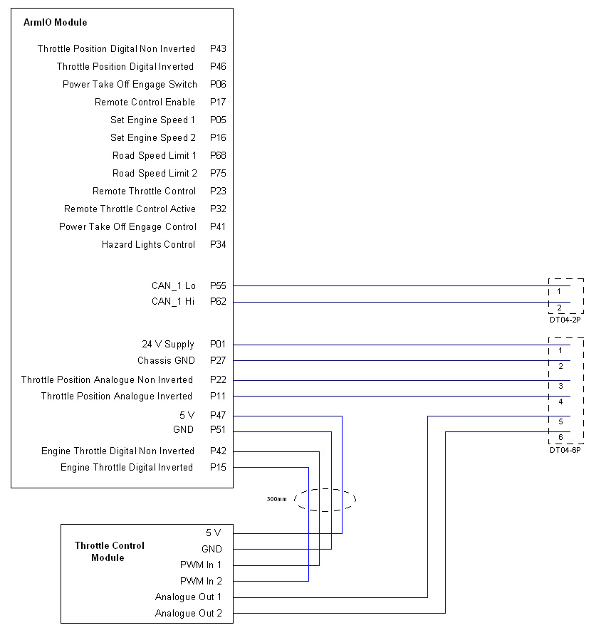
Wiring Schematic
Connection diagram showing the EVNet™ ARMIO module pinout, CAN bus connector, and throttle control module wiring.
Questions about the PTO Remote Throttle Controller?
For sales enquiries, installation scope, or to discuss your vehicle and application, contact Autokraft Electrical and Diesel.
Contact Autokraft Electrical and Diesel